Tag: ZDEC Service Manual, ZDEC V8/ V9705 / 97059 Service, LED Display Control System Commissioning, LED display after-sales service

VERYPIXEL is specialized in LED display R& D, production and manufacturing companies, we are committed to providing customers with a variety of ☞ LED Display Solutions ☜ , and to provide you with quality products pre-sales, after-sales service.
1. The Chart of PC, System & LED Screen connection

Figure 1-1 Single sending card application
Solution Introduction: In fig1-1,1 indicates the computer, 2 indicates the sending card, 3 indicates the receiving card, and 4 indicates the environmental monitor. The sending card has 2 output ports, U port& D port. Receiving cards are connected in series-wound condition. Monitor can be fixed behind U port or D port (Note: Not allowed fixing the monitor into both ports at the same time or fixing no monitor is also acceptable), it is used to real time monitor brightness, temperature and humidity of the LED display screen. The max number of equipment cascade-connected in each port is 200.
2. Computer & Install
Operating environment
● Operating system
Windows2000/ XP Chinese and English version
● Hardware
CPU: Celeron 2.4G or higher
Memory: 1G or higher
Graphics: 32M or higher
● Related Software
Video Decoder—compulsory (install special decoder when play RM or RMVB format file)
2.1 Install
<LED manager 2010> software is easy to be installed. Firstly , to check whetherthe computer has old version of LED manager tool, please un-install it if exists.Secondly, double click LED manager file and then the dialogue box pops up, see Fig 2-1, then according to the tips to install the software. When the installation of <LED manager 2010> Is made, the"LED software" will appear in the <Start/ Program>, Click to start operation after entering <LED manager 2010> in the program as Fig2-2 shows.

Fig2-1
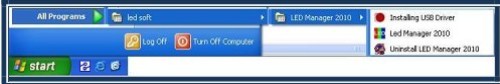
Fig2-2
And there is a shortcut of <LED manager 2010> on the desktop as icon shows,
Double-click it also can start the program.
2.2 Un-install
《LED manager 2012》software provides an auto-uninstall function, for your convenience to delete all “LED Manager 2010”files, program groups and short-cuts. Users can either select “Delete LED Manager 2010” under the “LED Software” group as figure2-2,or go to <control panel>,select <add/delete program> to undergo quick uninstall. After clicking on the delete, the pop-up dialog box will ask for confirmation, confirm it and the software will be uninstalled automatically.
3. Use Details and Computer Parameter setting
In this chapter, we will use NVIDIA Graphics card an example to illustrate the setting method of Graphics card. Different setting methods are subject to different graphics card brands and models, please note this chapter is only for reference, and you should accord to practical situation to set the actual graphics card model. Please noted it is only for reference, so the actual Graphics card must be respectable when setting.
To be assured the text displayed in LED screen is the same as in computer monitor, we must set the multiple outputs of graphic card(VGA and DVI outputs usually)as copy mode.
Generally, LED display system is set as main equipment; monitor is set as subsidiary equipment. The description of details as below:
3.1 Start the computer, right-click mouse button, select the < Attribute >, enter the dialogue window of < display attribute>.
3.2 In this interface, select “setting”, click the “advanced” button at the lower right corner. See Fig 3-1
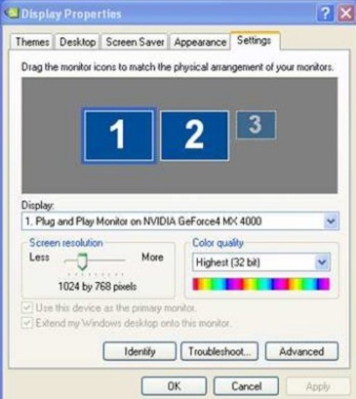
Fig3-1
3.3 When popup dialogue window 【Plug and Play Monitor and NVIDIA GeForce6200】,select【GeForce6200】menu, click the "nView" display setting menu in extra-menu of left side. See fig3-2
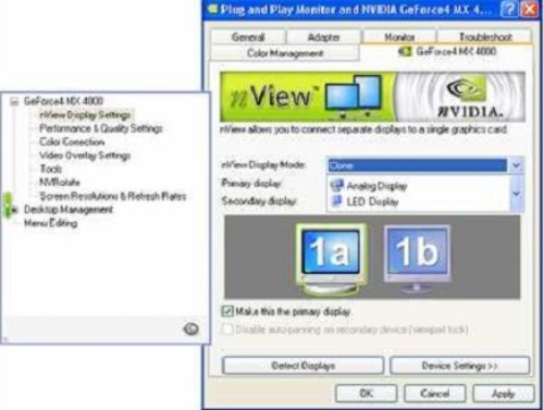
Fig3-2
3.4 There are 2 options in the interface, Click pull-down menu in“nView”, Select “Clone Display”. Then click “save”button, back to main interface, see Fig 3-3
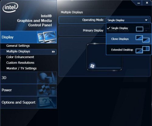
Fig3-3
After the above setting steps, the clone mode of Graphics DVI port has opened, observe and confirm the indicator of transmitting card if correct.
4. Program operation process
4.1 Step 1: Set the size of Play window
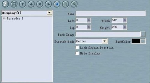
Fig4-1
The size of Play Window must be set correctly; otherwise the program may onlydisplay a part because the play window is not big enough.Set Method: <Menu> →<Setting> →<Display setting>,as shown in Fig 4-1,you canLock display position in the set of software.
Left boarder and upper border(X,Y) are set to (0, 0) to ensure the Play Window in the upper left corner of the screen. And set the width, height, according to the size of your screen, such as your screen width and height is 512 X 256, and then set to (512, 256).
4.2 Step 2: New episodes
Episodes are the basic element of the program. The toolbar as shown in Fig 4-2,
Click the button<new> and the main menu pop-up, you can click on episodes. Program can contain any number of episodes. And the function button includes<Delete>, <Move up>, <move down> and <Zoom in>, <Zoom out>.
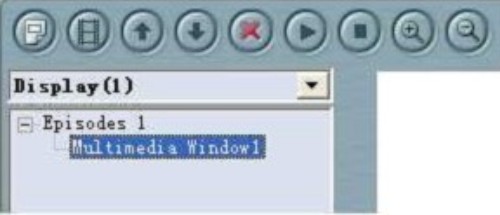
Fig4-2
4.3 Step 3: Set the options of episode
As Fig 4-3 shows, the options of episodes includes <name>, <Play Option>, <Timer/Play>, and <Background Music>
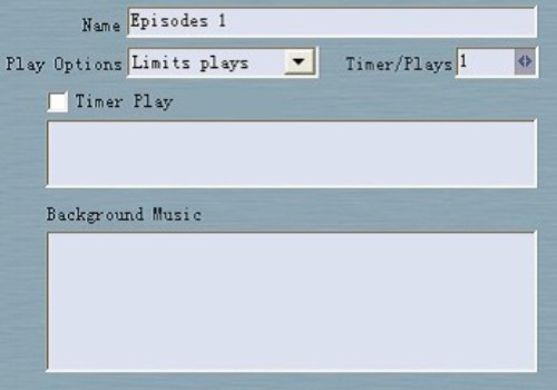
Fig4-3
4.4 Step5: New Multimedia window
Episodes are only a framework, it contains any number of multimedia windows. Click the button<New> and select the <Multimedia Window>, as shown in Fig 4-4.
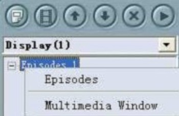
Fig 4-4
4.5 Step5: Set property of Multimedia window
Each Multimedia window can set the attributes of<Location>, <size>, <Background>,<Transparency>, as shown in Fig 4-5.
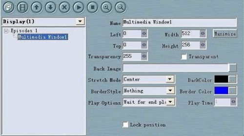
Fig 4-5
Transparency: The transparency of the background of the media window.
Transparent background: on/ off transparency.
Maximize: Media windows full with play window.
Back image: The background image of media window.
Stretch Mode: background color of the media window.
Back color: border color of media window.
Border Style: border style of windows media.
Border color: border color of media window.
Play options: used to set the play time or times of multimedia window.
Episodes play, Set as the benchmark: the end time of episode if based on the time of this multimedia window. For example: episodes includes ten multimedia windows, if you select this option in the third multimedia window interface, then when the third multimedia window finishes playing, other multimedia window are stop playing at the same time.
Lock position: Lock location of multimedia window.
4.6 Step 6: Add Multimedia Material
Each multimedia window can simultaneously play different tests, pictures, tables, animation and video. There are 12 kinds of multimedia material for choice, as shown in Fig.4-6
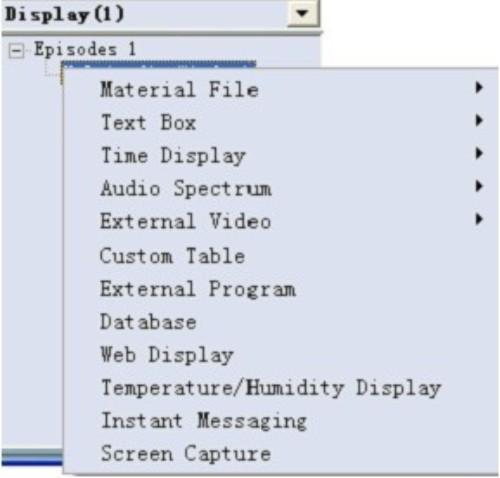
Fig4-6
Material File: the most important material, including picture, video, Flash, Word and Excel and other formats of media files.
Test box: used to play text files, such as: Notice, advertisement text, You can add single-line text, multi-line text and the word special Flash effects(default rate of 12 frames/sec).
Time display: used to display time. Include the clock display, timer time.
Audio Spectrum: including audio visual images and audio spectrum image.
External Video: used external camera or SDK3000 video card, to connect other Video equipment such as TV, VCD/DVD, VCR.
Custom Table: used to edit and display the tabular data.
External program: For embedding the external program into the display window, mainly for playing small programs user developed for themselves.
Data base: Use to display the database file. Include ACCESS database and ODBC databases.
Web display: used to display web pages.
Temperature/Humidity Display: use to display the current environmental temperature and humidity.
Instant Messaging: used to quick a short text, such as notification letter.
Screen capture: used to record the current screen image inside the window.
4.7 Step7: Set property of multimedia material
For each of the properties of multimedia material, we will point out in the later chapter. You need to create multimedia form type upon needs, find the corresponding chapter, which can obtain more detailed property information.
4.8 Step8: Finish program production
After eight steps above, a complete program can be completed. If need more episodes, just repeat step2 to step7. When finished, click the drop-down menu→<File>→<Save project> or <Save project as> to facilitate the next use.
4.9 Step9: Play program
Click the button <play> in the control to start playing shows,<Pause>button and <Stop>for stop playing.
5. Trouble Shooting
5.1 The Whole Screen Blindness
Solution:
a. Check if the power supply of the whole screen is normal.
b. Check whether the indicating lights of the sending card and receiving card are in the normal working condition or not. The normal working condition of the sending card is the green light twinkling, red one keep blind, as to the receiving card, one green light twinkling, the other keep lighting.
c. Click into the setting configuration of the software, to check whether the close option of the screen has been chosen.
d. If all the above are correct, then resend the screen connecting file, the operation is as follows:
Open the “LED Manager 2010",click the hardware setting under "setting”,it includes all the main setting of the screen. (see Figure5-1)
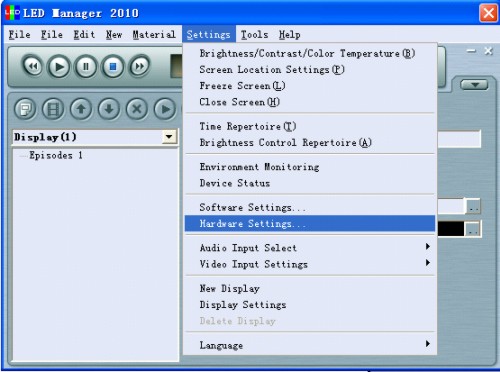
Fig5-1
While the"hardware setting" is opened, and at least, one sending card and the PC USB port are correctly connected, please input the words orderly "z","d","e","c"(capital or not is ok), and then an password window will come out.(see Figure5-2)
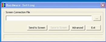
Fig5-2
Input the password “168” and click “confirmation” to enter into the “Advanced hardware setting” window (see Figure 5-3) (Note: the Advanced hardware setting is for professionals only, the common user is not recommended)
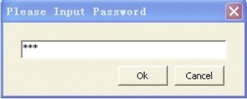
Fig5-3
Click the “Screen Connection” button to enter into the screen settings(see Figure 5-4), the Screen Connection mainly sets the connecting conditions o the screen, if stored such files before, then you could click the button” Load from File” to load it from the existing file.
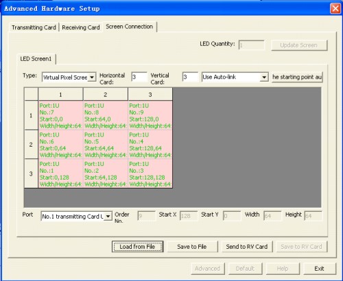
Fig5-4
5.2 LED screen partial abnormal display
Solution: Click the “Device Status” under the setting option, see under Figure(5-5)
Checking the transmitting card status, and then click the “Start Detection” button(Figure5-5) to check whether there are default data, if yes, please check one by one the connection between the current receiving card and the prior one.
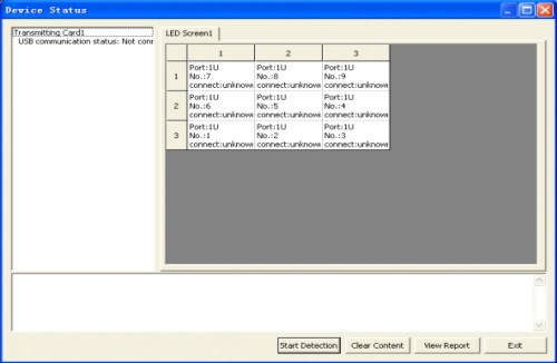
Fig5-5
6. Special Function Instruction
6.1 Point to point correction
6.1.1 Start the “LED manager 2010” (see Figure 6-1)
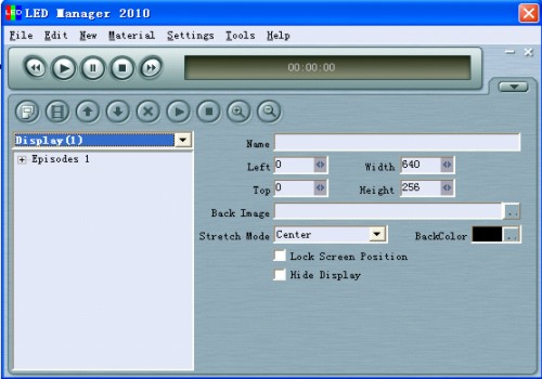
Fig6-1
6.1.2 Select Point to Point Correction Function
After the setting of the screen, click the "Screen Correction" under the "Tools" option.(see Fig 6-2)
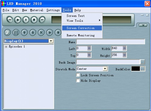
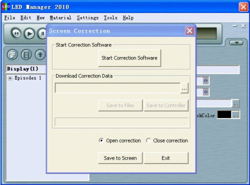
Fig6-2
6.1.3 Check the Correction Result
Select "Open correction" under the "Screen Correction", then click the button "Save to Screen"(see Figure 6-3) , and now you could check the correction result on the screen.
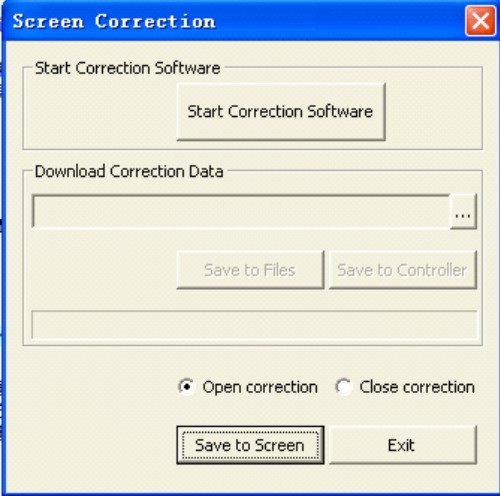
Fig6-3
6.2 Environment Monitoring
6.2.1 Installation Instruction
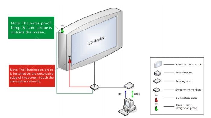
Fig6-4
Notice: Environmental monitor is combined with the temperature and humidity probe for use. The temp&humi.probe is with shield and free of wind and water (the rain), so it can be installed outside the screen. Illumination probe is also wind and water resistance, and generally installed on the decorative edge (frame) of the screen, with the same direction as that of screen face.
6.2.2 Software Operation
After connecting the Environment Monitor and installing the probes, open the "LED Manager 2010",click the "Environment Monitoring" under the menu of "Settings" (see Figure 6-5)
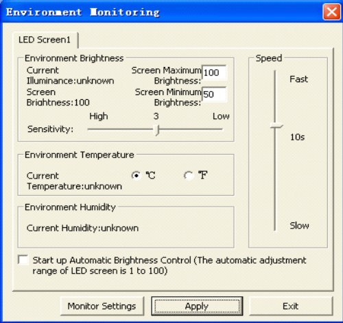
Fig6-5
In "Environment Monitoring", it lists the specific data of the current brightness, temperature, and humidity. Besides, if we add the temperature and humidity window in the playing program, the temperature and humidity parameters will real time display on the screen.
In "Environment Monitoring", click the "Monitor Settings",you can set some parameters for the environment monitor (see figure6-6 below).The sending card's port connected with the monitor should be set correctly, otherwise the software can not read the data correctly. Additionally, from this window we can find: the recommended brightness probe scope is 0-4000Lux, temperature probe scope is -10-60 Celsius Degree, and humidity probe scope is 0-100%RH.
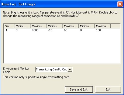
Fig6-6
The software offers” Start up Automatic Brightness Control” check box, and if this item is selected, when the software finds the monitor the software will adjust the illumination automatically according to the brightness value. If this item is not selected, the software just indicates the brightness value but won't adjust the brightness automatically according to the monitoring.“Start up Automatic Brightness Control” is not selected as the default setting.
The software window offers four options for LED screen: Minimum Brightness, Maximum Brightness, Current Brightness, and sensitivity.
● Minimum Brightness: It indicates the minimum brightness of the screen (never less than it) when the screen is automatically controlled by the monitoring device. The maximum value is 100, the minimum value is 1. (Filling in integer between 1 to 100,not allowing the decimal).This value is set by customer and the original default value is 50.
● Maximum Brightness: It indicates the maximum brightness of the screen (never exceed it), when the LED screen is automatically controlled by the monitoring device. The maximum value is 100; the minimum value is 1(Filling in integer between 1 to 100,not allowing the decimal).This value is set by the customer, and the original default value is 100.
● Current Brightness: It shows the data of brightness synchronously with the monitoring. This number is restricted by the Maximum and Minimum Brightness, it is between them.
● Sensitivity: It supplies five ranks of choice, it decides between what scope of the environmental brightness that the monitor will react.(See the follow figure 6-7)
|
Sensitivity
|
1(Maximum)
|
2
|
3 (Default)
|
4
|
5(Minimum)
|
|
Responding scope
|
0 to 4000Lux
|
0 to 4000Lux
|
0 to 1200Lux
|
0 to 800Lux
|
0 to 500Lux
|
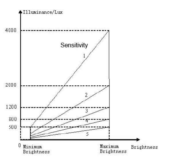
Fig6-7
All the data could be adopted according to the requirement, we could set up the "sampling rate", we could choose 1s, 5s,30s,60s,300s,600s, and this data decide the frequency that the software refreshes brightness, humidity and temperature. For example, if we choose the sampling rate at 600s, then the every 600s, the software refreshes the brightness, humidity and temperature, meantime conduct a brightness automatic adjustment. The original default setting is 10s.
The priority of the Automatic Brightness Adjustment, Timing Brightness Adjustment, and Manual Brightness Adjustment is set forth below:
● Whether the Automatic Brightness Adjustment or Timing Brightness Adjustment is adopted, the Manual Brightness Adjustment is available.
● When adopt the Automatic Brightness Adjustment, the Timing Brightness Adjustment is void.
6.3 Fiber Optical Transmitting
In the diagram below, device 1 is PC, device 2 is sending card, device 3 is receiving card, device 5 is photoelectric converter. The devices are usually connected with CAT-5E, and this cable's transmitting distance is 100M.If the distance is more than 100 M, we propose to adopt optical fiber transmission. Between two devices, we use CAT-5E and photoelectric converter to connect, and between two photoelectric converters we use optical fiber to connect. Multimode fiber's transmission is more than 500M, single mode fiber 'transmission is up to 10KM.Note: between every two devices, photoelectric converter can be adopted to prolong the transmitting distance.
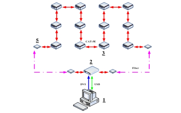
Fig6-8
Page address: http://www.verypixel.com/service/ZDEC_Service_Manual.html